The latest industry standards and knowledge of air conditioning water pumps
The air conditioning pump is a water pump designed for sewage discharge. The air conditioning water pump is suitable for the drainage needs of heavy and polluted condensate water, and can be used for the discharge of high-temperature and weakly acidic condensate water (temperature 46-95 ℃). It can be used in air conditioning systems and refrigeration equipment.
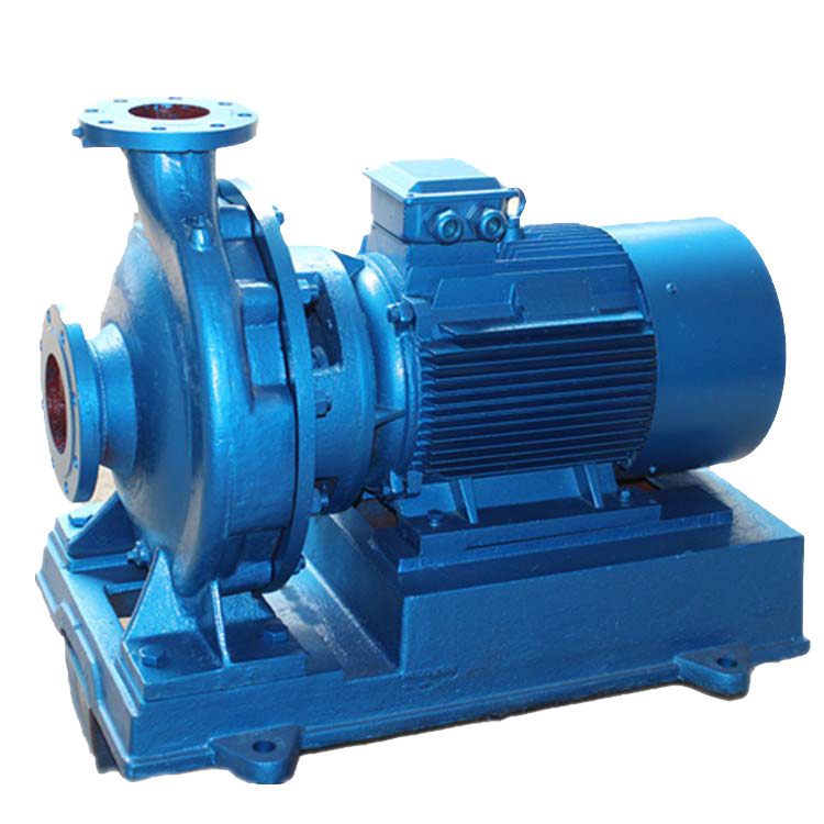
Mechanical structure
summary
The air conditioning water pump is suitable for pressurized household water supply and cooling systems, air conditioning systems, horticultural irrigation, and small industrial water supply systems. It has a compact, sturdy, reliable, and low noise structure.
The air conditioning water pump is a circulating water pump suitable for cold water, cooling water, and hot water in the central air conditioning system of high-rise buildings. It can also be used in the supply and drainage systems of other projects. Its conveying medium is clean water or other liquids with physical and chemical properties similar to clean water. The suitable medium temperature is not higher than 80 ℃, and the pressure bearing part of the air conditioning water pump has a pressure resistance of 1.6MPa.
Related parameters
Flow range: Q: 10-3000m ³/ h. Head range: H: 8-120m. The driving force of the pump is directly provided by the electric motor through the elastic ring pin coupling. The rotation direction of the air conditioning pump is clockwise when viewed from the driving end.
Adopting 104 type tungsten carbide hard alloy mechanical seal and imported SKF series bearings.
characteristic
Rear opening structure, easy maintenance, stable and reliable operation, long service life, low noise motor, about 10dB lower than similar products.
Before leaving the factory, it undergoes a 2.4MPa pressure resistance test to ensure safe use. The open structure is easy to maintain, without the need to disassemble the pump body and inlet and outlet pipes. It has a wide range of versatility, with only four specifications of shafts, bearings, and coupling covers, reducing spare parts and facilitating maintenance management.
There are sealing rings in front and behind the impeller, and a balance hole is installed on the rear cover plate of the impeller to balance the axial force and wear resistant mechanical sealing device of the pump, ensuring no water leakage under high water pressure. The lubrication structure of bronze impeller, stainless steel shaft, and imported bearing bearings is divided into two types: dry grease lubrication and wet mechanical oil lubrication.
Adopting world-class design software and hydraulic models, utilizing advanced vacuum casting technology.
The main components are processed using a CNC lathe, and all impellers have undergone strict dynamic balance testing, with a double vortex shell structure design.
Adopting high-quality mechanical seals, with a variety of mechanical seals to choose from, the lubrication device is easy to place, and can be quickly repaired. The lubrication is reliable and high-quality, with double row thrust and short ball bearings, and a service life of up to 5 years.
Multiple materials such as all cast iron, all bronze, and special alloys are available for selection. The installation base is matched with the motor groove, and the vertical structure has advantages such as small footprint, allowing for linear connection in any direction, and preventing water flooding in high-level motors.
The pump is a vertical structure with the same inlet and outlet diameters and located on the same centerline. It can be installed in pipelines like a valve, with a compact and beautiful appearance, small footprint, and low building investment. If a protective cover is added, it can be used outdoors.
The impeller is directly installed on the extended shaft of the motor, with a short axial size and a reasonable configuration of the pump and motor bearings, which can effectively balance the radial and axial loads generated by the pump operation, thereby ensuring smooth operation of the pump and low vibration noise.
Easy installation and maintenance, no need to dismantle the pipeline system, as long as the pump coupling seat nut is removed, all rotor components can be extracted.
The pump can be operated in series or parallel according to the requirements of flow rate and head.
According to the requirements of pipeline layout, pumps can be installed vertically and horizontally. Series flow range 1.5-1600m ³/ h. The head range is 5-125m, with various specifications including basic type, diversion type, cutting type, etc.
mechanical principle
The air conditioning water pump equipment consists of a temperature and pressure sensor system, a PLC control system, a variable frequency speed regulation system, a touch screen system, and a cold water (heating) or cooling water pump. The closed-loop control system compares and distinguishes the feedback values of temperature difference and pressure difference in real time with the set target values. The PLC system automatically adjusts the operating frequency of the water pump to achieve the maximum energy-saving goal while meeting the process requirements.
As the working conditions change, the frequency of the water pump motor controlled by the equipment always changes while meeting the requirements. As the frequency decreases, the noise decreases, and the motor temperature decreases, it not only saves electricity but also extends the service life of the equipment. The economic and social benefits generated from this are very objective.

According to this principle, the IAO-PF-I energy-saving control equipment automatically adjusts and controls the start/stop and speed of the water pump, increases the temperature difference to the specified range or meets the actual requirements, reduces the flow rate of the water pump, and correspondingly reduces the power consumption of the water pump motor, achieving significant energy-saving.
Application limitations: IAO-PF-I energy-saving control equipment is not suitable for central air conditioning systems and heat exchange systems. The temperature difference between the inlet and outlet water is already large and close to the national standard of 5 ℃.
Power consumption expression for pump station N=K1 X Q X H/ η, In addition to the IAO-PF-I model, which introduces increasing temperature difference to reduce pump station flow rate Q and pump station reduction
In addition to reducing the power consumption of pumping stations through the control method of head (pressure) H, it can also improve the overall operational efficiency of pumping stations η To reduce power consumption, the National High tech Industrialization Major Project - Pump Station Quantitative Energy Saving System, through system optimization, optimizes the combination and speed regulation operation control equipment of pump units with low power consumption while meeting process requirements, achieves quantitative energy-saving control of pump units, and can achieve maximum operational efficiency of pump stations η Max, even if there is no temperature difference in the central air conditioning system, significant energy savings can still be achieved.
The IAO-PF-I type quantified energy-saving control equipment for air conditioning water pumps can be applied to all central air conditioning systems, regardless of whether there is temperature difference margin or no temperature difference margin. This equipment can also be used for energy-saving transformation of pump stations (groups) with existing frequency conversion and other energy-saving equipment to achieve maximum energy savings.
The IAO-PF-I type quantitative energy-saving control equipment can make the refrigeration pump, cooling pump, and heating pump group of the central air conditioning system save energy to the fullest in one go.
Mechanical Core
The important structure of the air conditioning water pump is the internal compressor structure. The high silicon aluminum alloy inclined plate is pressed into the main shaft and integrated into the front and rear cylinder bodies of the aluminum alloy, supported by needle roller bearings and end face bearings. The piston is mounted on the inclined plate with two hemispherical sliding shoes, and the five pistons are evenly arranged in the cylinder body at a 72 ° angle in the circumferential direction.
On the end faces of the front and rear cylinder blocks, there are suction valve plates, aluminum alloy valve plates, and limiters composed of exhaust valve plates. Circular suction and exhaust chambers are set on the front and rear aluminum alloy cylinder heads, which are respectively connected to the intake and exhaust channels on the cylinder block. Above the center of the front and rear cylinder blocks, there are intake and exhaust ports connected to the refrigeration system.
The sealing ring and shaft sealing device of the air conditioning water pump ensure the sealing inside the compressor. The clutch is connected to the main shaft through a key, and the coil and pulley are installed on the front cylinder head. The pulley is driven by the engine crankshaft pulley through the belt.
After the compressor is turned on, due to the action of the coil, the pulley sucks the clutch together and rotates, driving the main shaft to rotate. The inclined plate then rotates and swings on it, causing the piston riding on the inclined plate to move back and forth.
The five pistons move back and forth, with air intake and exhaust at their respective ends, thus becoming a bidirectional ten cylinder compressor.
The compressor is an important component in the refrigeration system, which plays a role in compressing and transporting refrigerant gas. It generates refrigerant gas in the evaporator, enters the compressor, is compressed, and then sent to the condenser for cooling.
The refrigerant gas enters the compressor through the intake ports on the front and rear cylinder blocks, and then enters the annular suction chambers on the front and rear cylinder heads respectively. Due to the movement of the piston, the suction valve plate is opened to suck in gasoline, which is then discharged into the annular exhaust chambers on the front and rear cylinder heads through the exhaust valve plate, and then discharged through the exhaust ports on the front and rear cylinder blocks.
The lubrication of the moving parts of the compressor relies on two methods: first, the refrigerant itself contains oil and is self lubricated; The second is splash lubrication.
In the Audi 100 refrigeration system, the total oil injection volume is 300ML, and the compressor only accounts for 80ML. The oil added to the compressor is stored in the pit set at the bottom of its cylinder body, and an additional 220ML is added to the liquid separator.
During compression work, due to the rotation and swing of the inclined plate, the refrigeration oil in the pit is splashed everywhere by the inclined plate.
In addition, due to the completely miscible nature of refrigerant and oil, when refrigerant flows into the compressor, it also carries some refrigeration oil to lubricate the moving parts inside the compressor.
Mechanical maintenance
Pre start inspection and maintenance:
1. Is the lubricating oil for the bearings of the air conditioning water pump sufficient and in good condition;
2. Check if the anchor bolts and coupling bolts of the air conditioning water pump agent motor are loose or detached.
3. Whether the air conditioning water pump and inlet pipe are fully filled with water;
4. Whether the bearings are leaking or dripping (the number of drops per minute meets the requirements);
5. For horizontal air conditioning water pumps, it is required to manually rotate the coupling to check if the impeller of the water pump can rotate. If it cannot rotate, the cause must be identified and hidden dangers must be eliminated before starting.
B. Start up inspection and maintenance:
1. Determine whether the rotation direction of the air conditioning water pump shaft (impeller) is correct;
2. Whether the rotation is flexible and whether there is any jamming phenomenon;
C. Operation inspection and maintenance:
1. The motor should not have excessive temperature rise or produce any odor;
2. The bearing temperature shall not exceed the ambient temperature of 35 ℃ -40 ℃, and the maximum temperature limit of the bearing shall not exceed 80 ℃;
3. There is no water leakage at the shaft seal (except for the specified form of dripping) and the connecting head;
4. No abnormal noise and vibration;
5. There is no looseness in the nuts of the anchor bolts and other connecting bolts;
6. Whether there is obvious deformation in the connection of the inlet and outlet water pipes;
7. Is the current within the normal operating range;
D. Regular maintenance and upkeep:
a. For those lubricated with lubricating oil, they should be cleaned and replaced once a year;
b. For air conditioning water pumps lubricated with grease, they should be replaced every 2000 hours of operation;
c. For those sealed with packing, if water leakage or the number of leaking droplets exceeds the standard, they should be compressed or replaced;
d. If mechanical water seals are used, they should be replaced according to the inspection results;
e. Disassembly and maintenance: Conduct an annual disassembly and maintenance of the water pump, mainly including cleaning and inspection;
f. Rust removal and painting: Once a year, rust prevention treatment should be applied to the air conditioning water pump body that has not been insulated.
Product Usage
Air conditioning water pump is an ideal new type of high-efficiency energy-saving pump, widely used for household water intake, underground pumping, pressurized tap water, garden irrigation, vegetable Dapeng water supply, industrial and mining enterprises, and animal husbandry.
technical standard
GB/T 18837-2002 Multi unit Air Conditioning (Heat Pump) Units
GB 21454-2008 Energy Efficiency Limits and Energy Efficiency Grades for Multi unit Air Conditioning (Heat Pump) Units
GB/T 18836-2002 Ducted Air Conditioning (Heat Pump) Units
GB/T 22069-2008 Gas Engine Driven Air Conditioning (Heat Pump) Units
GB/T 27941-2011 "Application Design and Installation Requirements for Multi unit Air Conditioning (Heat Pump) Units"
GB/T 50114-2001 HVAC Drawing Standards
GB/T 14294-1993 Combination Air Conditioning Units
GB50243-2002 "Code for Acceptance of Construction Quality of Ventilation and Air Conditioning Engineering"
GB50365-2005 Code for Operation and Management of Air Conditioning and Ventilation Systems.